

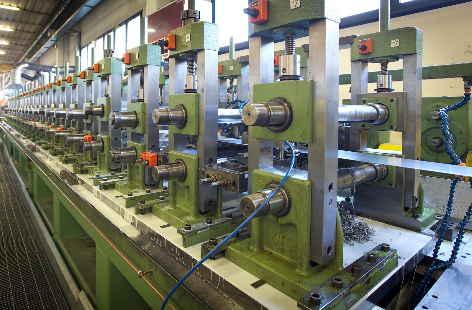
For continuous profiles, long structural sections, and high-volume linear components—such as architectural standing-seam roofing, highway guardrails, structural steel studs, and automotive bumper beams—traditional press brake bending and discrete sheet metal stamping become major production bottlenecks. Continuous Roll Forming solves this throughput challenge by progressively shaping a continuous strip of metal through a tandem series of contoured roller die stations.
Unlike deep drawing or press brake bending, which deform large surface areas simultaneously, roll forming applies incremental bending localized strictly at active roll contacts. This localized deformation allows manufacturers to produce complex cross-sectional profiles of virtually unlimited length at speeds exceeding $30 text{ to } 100 text{ meters per minute}$, all while maintaining tight cross-sectional dimensional tolerances and high surface finish quality.
1. Mechanics of Incremental Roll Bending
Roll forming transforms a flat metal coil into a complex three-dimensional profile through incremental cold deformation. As the strip travels linearly through successive roll passes, each station performs a small step of the total required angular bend.
INCREMENTAL BENDING PROGRESSION THROUGH ROLL PASSES
Flat Strip Pass 1 (15°) Pass 2 (45°) Pass 3 (90° Final)
————– /———– /————- |————-|
| | | | | |
The Flower Diagram: Deconstruction of Profile Geometry
The foundation of roll forming tool design is the flower diagram. By superimposing the cross-sectional profile of every roll station onto a single reference plane, tool engineers map the progressive geometric transformation of the material from flat stock to its final shape.
SUPERIMPOSED FLOWER DIAGRAM
Station 4 (Final 90°)
| |
Station 3 (60°)
/
Station 2 (30°)
______/
Station 1 (Flat/10°)
——————
Designing an effective flower diagram requires balancing two competing mechanical constraints:
-
Too Few Passes (Excessive Strain): Bending the profile too aggressively over few stations induces severe longitudinal stretching along the outer edges of the profile. This leads to end-flare, twisting, and edge wrinkling.
-
Too Many Passes (Excessive Capital Cost): Unnecessarily increasing the number of roll stations raises tooling costs, extends line length, and increases total machine drive power requirements.
2. Longitudinal Strain and Deformations
Because the outer edges of a metal sheet travel a longer physical path than the central neutral axis when transitioning from a flat profile to a three-dimensional shape, the strip experiences temporary longitudinal tensile strain between roll stations.
LONGITUDINAL STRAIN PATH BETWEEN STATIONS
Station N Station N+1
+——-+ +——-+
| Roll | | Roll |
+——-+ +——-+
/ /
Edge Path (Longer) / /
—————–>+——————-+—————–>
Center Path (Short)
If the peak longitudinal strain experienced during forming exceeds the material’s yield strength ($sigma_y$), permanent elastic-plastic defects develop:
+———————————–+
| ROLL FORMING STRUCTURAL DEFECTS |
+—————–+—————–+
|
+—————————+—————————+
| |
+—–+—–+ +—–+—–+
| Geometric Distortions | | Edge Instabilities |
+———–+ +———–+
• Camber (Horizontal bowing) • Edge Wrinkling (Flange buckling)
• Bow (Vertical curvature) • End-Flare (Springback at cut ends)
• Twist (Axial rotation along length) • Splitting (Tensile fracture along bend)
Key Defect Mechanisms
-
Camber, Bow, and Twist: Caused by asymmetric strain distribution across the cross-section or uneven drive roll pressure between the left and right sides of the machine frame.
-
End-Flare: Occurs when residual internal stresses in a roll-formed profile are released during cutoff, causing the cross-sectional ends of the part to spring open or contract relative to the mid-body.
-
Edge Wrinkling: Occurs when thin flanges undergo excessive longitudinal compression after leaving a roll pass, buckling the thin edge before it stabilizes in the next station.
3. Roll Forming Line Architecture and Sub-System Integration
A complete roll forming line operates as a continuous automated system comprising material handling, forming, and inline secondary manufacturing sub-systems.
CONTINUOUS ROLL FORMING LINE ARCHITECTURE
+———–+ +————+ +————+ +————–+ +————+ +———–+
| Uncoiler |—>| Pre-Cut / |—>| Roll Form |—>| In-Line |—>| Flying |—>| Run-Out |
| & Splicer | | Pre-Punch | | Mill | | Welding/Form | | Cut-Off | | Table |
+———–+ +————+ +————+ +————–+ +————+ +———–+
Core Sub-System Components
-
Uncoiler and Coil Accumulator: Expands internally to hold heavy raw metal coils (up to 20 metric tons). The accumulator loops material continuously, giving operators time to splice the end of a finished coil to a new coil without stopping the main roll mill.
-
Pre-Punch / Pre-Notch Unit: High-speed hydraulic press units that punch hole patterns, slot grids, and notch boundaries into the flat strip before it enters the forming rolls, eliminating complex multi-axis punching on a fully formed profile.
-
Roll Form Mill (Pass Stands): Consists of a rigid drive chassis housing alternating top and bottom horizontal shafts (arbors) that hold the hardened tool steel roll dies. Vertical side-roll stands guide flanges and control lateral material movement.
-
In-Line High-Frequency Induction Welding: Used in tube and pipe roll forming mills. As the open profile is rolled into a circle, high-frequency current heats the mating strip edges to fusion temperature, and squeeze rolls press them together to create a continuous solid-state forge weld.
-
Flying Cutoff System: A high-speed die accelerator matches the linear speed of the moving profile, driving a shear blade or cold saw through the part to produce clean lengths without interrupting mill motion.
4. Pre-Cut vs. Post-Cut Process Dynamics
Selecting between pre-cut (cutting flat blanks to length before forming) and post-cut (forming a continuous coil and shearing after roll exit) dictates line throughput, tooling cost, and end-flare control:
+———————————–+
| PRE-CUT VS. POST-CUT DYNAMICS |
+—————–+—————–+
|
+—————————+—————————+
| |
+—–+—–+ +—–+—–+
| Pre-Cut Architecture | | Post-Cut Architecture |
+———–+ +———–+
• Flat sheet sheared prior to forming • Continuous strip formed through mill
• Simple, stationary shear tooling • Requires complex flying cutoff unit
• High risk of end-flare & entry distortion • Superior end profile geometry control
• Ideal for short-run, variable-length parts • Standard for high-speed mass production
|
Performance Parameter |
Pre-Cut Architecture |
Post-Cut Architecture |
|
Capital Tooling Cost |
Lower (simple, low-tonnage stationary shear). |
Higher (requires high-speed, synchronized flying shear). |
|
Edge & End Quality |
Lower (leading and trailing edges flare as they enter and exit unconstrained rolls). |
Superior (continuous structural constraint prevents edge distortion prior to shear). |
|
Line Operating Speed |
Slower (requires gaps between individual blanks entering the mill). |
Extremely High (continuous operation up to $100+ text{ m/min}$). |
|
Part Length Flexibility |
High (instantaneous change of pre-shear cut length). |
Requires flying die control adjustments for different cut lengths. |
5. Tooling Metallurgy, Shaft Deflection, and Roll Calibration
Roll dies endure high continuous surface contact friction, sliding abrasion, and compressive stress. Maintaining micron-level cross-sectional accuracy requires matching roll materials to part specifications and managing shaft mechanics.
ROLL ARBOR DEFLECTION MECHANICS
Drive Load / Upper Arbor
|
v
+———————–+
/ | TOP ROLL |
/ +———————–+
/ |
Bearing Block | Workpiece Bearing Block
v /
+———————–+ /
| BOTTOM ROLL | /
+———————–+
^
|
Support / Lower Arbor
Shaft Deflection and Center Support
As metal passes through a roll station, the forming force pushes the upper and lower arbors apart. On wide profile mills, arbor deflection at the center of long shafts causes thickness variations, angle drift, and center-line bowing. Tool engineers counter shaft deflection by installing intermediate center-support bearings or designing subtle crown profiles directly into the roll dies.
Tool Steel Selection Guidelines
-
Standard Steel Profiles: Roll dies are machined from high-carbon, high-chromium tool steels such as AISI D2 or D3, vacuum heat-treated to $58–62 text{ HRC}$ and polished to a mirror finish to prevent surface marking.
-
Stainless Steel & Architectural Trim: Roll surfaces are hard-chrome plated or coated with PVD TiN/CrN to prevent metal transfer and galling.
-
Heavy Galvanized Coatings: Roll dies utilize specialized bronze alloys or highly polished tungsten carbide inserts to prevent zinc pick-up from galvanizing layers.
Summary
Continuous roll forming provides high throughput for manufacturing complex, uniform structural profiles of unrestricted length. By mapping progressive deformation with flower diagrams, controlling longitudinal tensile strains, integrating inline pre-punching and flying cutoff systems, and managing roll arbor deflection, manufacturers turn raw metal coils into high-precision structural components at industrial speeds.
Stainless steel pipes kampala uganda